高清日本在线成人免费视频-高清视频一区二区三区-高清一级-高清一区二区三区-高清一区二区三区视频

Pickering首頁
聯(lián)系銷售

技術支持
電子測試 | 虹科首頁 廣州虹科電子科技有限公司
PXI開關 PXI儀器和機架 PXI可編程電阻 LXI開關 PCI開關 PCI可編程電阻 其它模塊平臺 電纜和連接器 應用行業(yè) 關于我們
Pickering首頁 > 應用行業(yè) > 硬件在環(huán)仿真

利用PXI故障注入開關進行故障注入測試

Due to the high level of sophistication and complexity of today's Electronic Control Units (ECU) devices, special test methods are required. The idea of testing for system failures is not new, it is an important aspect of ECU validation and involves the introduction of electrical faults into a system (fault insertion testing). The test process typically duplicates various conditions which could occur because of corrosion, short/open circuits and other electrical failure inherited through age, damage or even faulty installation.

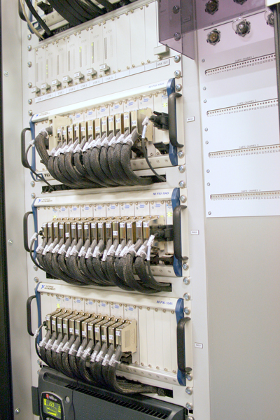
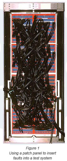
Typically, ECUs under development are exercised by a test system that simulates the device that the unit will control – this is sometimes called a Hardware-in-the-Loop (HIL) simulation. Stimulus instrumentation that simulates engine behavior, for example, is connected and controlled either by manual operation or by computer with measurement instrumentation used to capture analog and digital responses from the ECU. When it is necessary to inject faults, traditionally a patch panel, such as that shown in Figure 1, has often been used.

The various cables shown are used to connect any input/output (I/O) line of an ECU to stimulus or measurement instrumentation. The I/O lines may be manually disconnected to simulate an open-circuit or tied together to simulate short-circuits and the results measured. This type of solution has many inherent disadvantages, not least being size. There are also many hidden costs such as on-going maintenance issues, the need for significant knowledge on the part of the operator, potential human error and the cost of labor required to execute the test and record results.

Another major disadvantage of any manual method is the lack of repeatability. The ability to quickly reproduce a failed test condition is essential in a test system, either to aid development or to take corrective action. Being able to precisely reproduce the test procedure quickly is a major advantage in any upgrade or verification program.

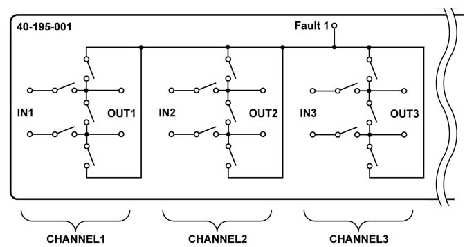
The ability to gain software control of both instrument routing and the insertion of real-time electrical faults enhances both the testing process and the recording of the outcome. However, although a standard crosspoint matrix with an adequate specification is capable of handling the instrument routing to the device under test, the insertion of faults requires a specific switching architecture.

  Figure 1 - Using a patch panel to insert faults into a system

Modular Fault Insertion Solutions

Pickering offers a comprehensive range of PXI Fault Insertion Unit (FIU) switch products . These scalable solutions may be used to switch signals between simulations and real-life devices in a multitude of HIL simulation and test systems. The FIUs can help to considerably simplify and accelerate the testing, diagnosis and integration work in HIL applications. The following are some of the most common fault insertion architectures (based on examples of our FIUs):

Single Fault Bus Architecture

This architecture shown in Figure 2 is used on our fault insertion modules (40-195 and 40-196) . In these two cases the input connections are grouped in pairs and then multiple pairs have a connection allowed to a single fault bus. Using this architecture a variety of faults can be simulated in the following ways:

  • Either input connection disconnected from its output
  • Input connection pair shorted together
  • Either input connected to the fault bus
The fault bus could be a power supply, system ground or some other connection in the system. If more than one fault bus condition is required to be simulated then additional (external) switching has to be used to expand the possibilities, or a different architecture used.
Figure 2 - Single Fault Bus Architecture


Figure 3 - Multiple Fault Bus Architecture

Multiple Fault Bus Architecture

This architecture, shown in Figure 3 below, provides greater flexibility and is used in a variety of our FIU modules . Using this architecture a variety of faults can be simulated:

  • Any input disconnected from its output
  • Any output connected to one of two fault buses
  • Any output shorted to any other output if the fault bus is disconnected

In the architecture used by our 40-190 series fault insertion modules , the fault bus can be disconnected or can be connected to any of four fault conditions, this allows the bus to connect to ground, a power supply or some other condition. As the connections are made with SPST switches setting them all open will allow the fault bus to be disconnected and permit a short between two signals to be created by closing two relays.?


Figure 3 - Multiple Fault Bus Architecture


Fault Insertion Matrix

Our fault insertion matrices (40-592 and 40-595) provide a more complex architecture that can be used in a variety of ways for complex fault insertion tests.

The common way of using the fault insertion matrix (shown in Figure 4) is for the connection between the controller and the sensor to be on the X axis. A connection from an input (for example) is made to X1.1 and its output from X1.2. In this example the default condition is for a connection to be made by the normally closed relay. Much more complex faults can be introduced:

  • Open circuit between input and output
  • Fault on the output to X1.2, which could be component inserted by a patch panel arrangement.Connection of any input to one of four fault buses (Y1 to Y4)
  • Connection of any output to one of four fault buses (Y5 to Y8)
  • Short circuits between wires by using an unused X column to provide the short on an unused Y row
  • Addition of other shunt components between wires using Y axis.

The variety of fault types that is simulated is large and the third connection on each X axis adds a great deal more flexibility.?

Figure 3 - Multiple Fault Bus Architecture

Figure 4 - Fault Insertion Matrix


Figure 4 - Fault Insertion Matrix

Our FIUs are available in a wide range of channel counts and fault bus configurations with current handling capabilities from 1Amp to 30Amp.?

The image to the right shows a high channel count automotive ECU validation system based on our PXI based fault insertion units (photo courtesy of Clemessy) and below are two examples of our PXI fault insertion modules.

Pickering's PXI fault insertion modules

To learn more about our modular fault insertion solutions , please contact us .

PXI based fault insertion system
 
虹科 > 電子測試 > Pickering Interfaces 專業(yè)測試測量用信號開關/可編程電阻/儀器
全部產(chǎn)品
PXI開關
PXI儀器和機箱
PXI可編程電阻模塊
LXI開關解決方案
PCI開關板卡
PCI可編程電阻板卡
其它模塊化平臺
電纜和連接器
應用行業(yè)
汽車
軍事和航空航天
射頻和微波
硬件在環(huán)
光學解決方案
其它公司的相關產(chǎn)品
Picotech測試測量產(chǎn)品
更多
我們是PXI聯(lián)盟創(chuàng)始成員

我們是LXI聯(lián)盟戰(zhàn)略成員


關于虹科
虹科積極進取,不斷探索科技新領域。最優(yōu)秀的員工和最好的技術能夠接受最困難的挑戰(zhàn)。為您找到最佳解決方案。虹科靠口碑贏得客戶。

Email 博客 論壇 點擊發(fā)送消息給我 

廣州:400 999 3848 | 上海:021-31215998 | 北京:010-57815068

sales@hkaco.com | 廣州虹科電子科技有限公司 | 版權所有 | 廣州市科學城神舟路18號潤慧科技園C棟6層    

主站蜘蛛池模板: 最近的免费中文字幕视频| 九九九国产在线| 三级黄色一级视频| 亚洲欧美日韩高清一区二区三区| 94在线成人免费视频| 免费观看黄色视屏| 国产乱码亚洲精品一区二区| 精品久久一区二区三区| 国产欧美综合一区二区| 欧美日韩黄色| 亚洲国产精品综合久久网络| 99久在线| 九九在线精品视频| 日本精品久久久久中文字幕 1| 成人看片黄a免费看视频| 国产精品va欧美精品| 黄频大全| 91亚洲区国产区精品区| 国产日韩欧美亚洲| 久久免费精品国产视频| 青青草国产青春综合久久| 亚洲精品国产精品精| 91在线看| heyzo国产亚洲高清| 久久有精品| 日本3级网站| 全免费a级毛片| 欧美一级毛片欧美一级| 国产91臀交在线播放| 国产在线精品一区二区不卡| 国产精品免费视频播放| 美国黄色一级大片| 黄网在线看| 黄色免费网站在线看| 精品国产一区二区麻豆| 91久久九九精品国产综合| 国产福利不卡| 亚洲成人性视频| 亚洲狠狠| 亚洲国产精品综合久久一线| 亚洲国产综合精品中文第一区 |